
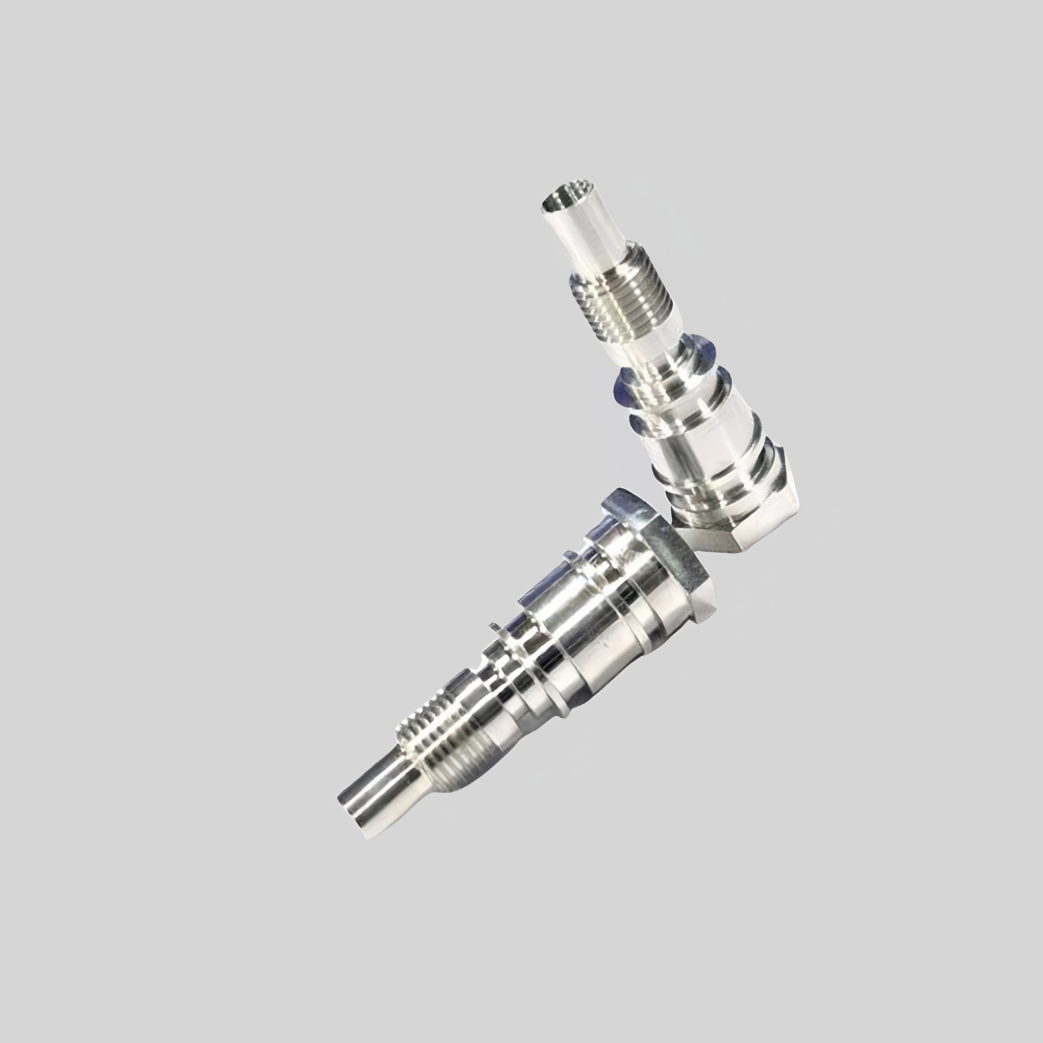
Overview of cnc metal parts Manufacturing
The Role of CNC in Modern Production
Computer Numerical Control (CNC) machining is a highly repeatable, automated method for transforming raw metal stock into precision components. Using programmed instructions, CNC machines control cutting tools along multiple axes with positional accuracy typically within ±0.005 mm to ±0.02 mm. This level of precision, combined with consistent repeatability over thousands of cycles, allows a manufacturer or factory to deliver complex geometries and tight tolerances that would be impractical with manual machining.
In a typical metal parts production line, CNC machining supports processes ranging from rapid prototyping of single units to Wholesale supply that may exceed 10,000 parts per month. The ability to switch programs and fixtures quickly makes CNC machining suitable both for high-mix, low-volume and low-mix, high-volume environments. This flexibility is crucial for suppliers serving automotive, aerospace, medical, and industrial machinery sectors, where design changes and variant management are routine.
Key Advantages for Wholesale and OEM Clients
For OEM and Wholesale buyers, CNC metal parts deliver three main advantages: dimensional consistency, scalable capacity, and cost control. Dimensional consistency is achieved by closed-loop servo control systems with position feedback resolutions often as fine as 0.001 mm, supported by rigid machine structures and thermal compensation algorithms. Scalable capacity comes from standardized programming workflows and modular fixturing, allowing a factory to ramp from sample runs of 5–10 pieces to batches of 5,000–20,000 pieces with minimal re-engineering.
Cost control is supported by reduced labor content, high material utilization rates (often above 85% for prismatic parts), and predictive maintenance. By monitoring spindle load, vibration, and cycle time trends, a professional manufacturer can maintain Overall Equipment Effectiveness (OEE) above 75%, which directly impacts per-part cost. When a Wholesale customer compares quotations, these efficiency metrics often explain price differences more clearly than hourly rates alone.
Understanding CNC Machines and Key Components
Main Types of CNC Machines for Metal Parts
Modern CNC metal parts are produced mainly on three machine families: CNC turning centers, CNC milling/ machining centers, and multi-tasking or mill-turn machines. CNC turning centers rotate the workpiece at speeds from 500 to 4,000 rpm (sometimes up to 6,000 rpm for small-diameter work) while tools move in 2 to 4 controlled axes. They are ideal for shafts, bushings, and threaded components up to several hundred millimeters in length.
CNC machining centers, typically 3-axis, 4-axis, or 5-axis, rotate or translate the cutting tool relative to a stationary workpiece. Spindle speeds often range between 8,000 and 15,000 rpm for general-purpose machines, with high-speed spindles exceeding 30,000 rpm for small tools and aluminum alloys. A 3-axis machine is sufficient for most prismatic parts, while 5-axis machines allow machining of complex, undercut, or freeform surfaces in a single setup, reducing cumulative tolerance stack-up.
Critical Machine Components Affecting Quality
The accuracy and performance of a CNC machine depend on several key components. The spindle, powered by a motor rated from 5 kW to more than 30 kW, determines maximum material removal rates. Linear motion is governed by ball screws or linear motors and guided by precision linear rails; combined positioning accuracy is often specified as ±0.01 mm over 300 mm travel, with repeatability down to ±0.005 mm or better.
Tool changers, with capacities typically between 20 and 120 tools, support automated, unattended machining. High-end machines integrate automatic pallet changers that reduce setup downtime to less than 2–3 minutes per batch. Modern control systems provide look-ahead functions (e.g., processing 200–1,000 blocks in advance), which maintain feed rates in complex contours and reduce cycle time by 10–30% without compromising surface finish.
From Design to CAD Models and Drawings
Converting Functional Requirements into 3D Models
The manufacturing process begins with a 3D CAD model that reflects the functional and assembly requirements of the metal part. Engineers define critical interfaces such as hole positions, sealing surfaces, and bearing seats. Dimensional tolerances for these features are typically in the range of ±0.01 mm to ±0.05 mm, while non-critical dimensions may allow ±0.1 mm to reduce cost. Surface finish requirements, usually expressed as Ra (arithmetical mean roughness), are set between Ra 0.8 µm and Ra 3.2 µm for most industrial components.
During the design stage, manufacturability is evaluated by checking minimum wall thickness (often recommended above 1.5–2.0 mm for steel parts), hole depth-to-diameter ratios (usually kept below 10:1 for conventional drilling), and tool access angles for multi-axis machining. Early collaboration between the customer’s design team and the CNC factory’s process engineers can reduce iteration cycles and shorten development lead time from 6–8 weeks to 3–4 weeks.
Technical Drawings and GD&T Specifications
While the 3D model defines geometry, 2D technical drawings translate it into actionable instructions for the manufacturing floor. These drawings include views, dimensions, tolerances, and Geometric Dimensioning and Tolerancing (GD&T) symbols. Typical GD&T controls might specify position tolerance of Ø0.02 mm for a hole pattern relative to a datum, or flatness requirement of 0.03 mm over a 100 mm plane. Such specifications directly drive process capability targets for the CNC manufacturer.
A Wholesale buyer should verify that the chosen supplier can interpret and measure GD&T requirements, often using Coordinate Measuring Machines (CMMs) with measurement uncertainty better than ±2 µm. Without this capability, compliance to tight tolerance drawings becomes a matter of chance, increasing scrap rates and field failure risk. Clear revision control on drawings and models is also essential to ensure that the factory always machines the latest version.
CAM Programming and Toolpath Generation Process
From CAD Geometry to CNC Code
Computer-Aided Manufacturing (CAM) software converts CAD models into toolpaths and then into G-code, the machine-readable programming language. The programmer defines machining strategies such as roughing, semi-finishing, and finishing, selecting appropriate tools, feeds, and speeds. For steel parts, cutting speeds typically range from 120 to 220 m/min for carbide tooling, while aluminum alloys may allow 300 to 800 m/min depending on rigidity and coolant delivery.
Feed rates are defined in mm/min or mm/tooth; for example, a 10 mm diameter end mill cutting aluminum might run at 12,000 rpm with a feed per tooth of 0.05 mm, giving a table feed of 2,400 mm/min for a 4-flute tool. CAM software optimizes step-over (often 30–70% of tool diameter for roughing) and step-down values to balance material removal rate and tool deflection. Errors at this stage can cause tool breakage, poor surface finish, or dimensional deviations exceeding specified tolerances.
Simulation, Optimization, and Cycle Time Estimation
Before sending the program to the shop floor, the CAM system simulates tool movement, checking for collisions with the workpiece, fixtures, or machine components. Advanced simulation can reduce crash risk by more than 90% compared to manual verification alone. The software also provides estimated cycle times for each operation; for example, a medium-complexity aluminum housing might have a roughing cycle of 8 minutes, semi-finishing of 4 minutes, and finishing of 3 minutes, plus 2 minutes for hole operations, for a total of 17 minutes excluding loading and unloading.
Cycle time analysis is critical for Wholesale pricing because machine time often contributes 30–60% of the per-part cost. If the factory can reduce cycle time by 15% through optimized toolpaths or higher feed rates, the savings directly improve the competitiveness of large-batch quotations. For a batch of 5,000 pieces, a 2-minute reduction per part translates to more than 160 machine hours saved, freeing capacity for additional orders.
Material Selection for CNC Metal Parts
Common Metals and Their Typical Applications
Material selection depends on mechanical, thermal, and corrosion requirements. Common CNC metals include aluminum alloys (e.g., 6000 and 7000 series) for lightweight structural parts, carbon steels (e.g., C45 or 1045) for shafts and gears, alloy steels for high-strength or wear-resistant components, and stainless steels (e.g., 304, 316) for corrosion-resistant applications. Yield strength can vary from 120 MPa for soft aluminum up to 1,000 MPa or more for quenched and tempered alloy steels.
Density differences also affect design and logistics. Aluminum’s density of about 2.7 g/cm³ is roughly one-third that of steel at around 7.8 g/cm³. For a part volume of 100 cm³, this difference translates to 270 g versus 780 g, which matters significantly for transportation and weight-sensitive assemblies such as aerospace or mobile equipment. A professional manufacturer will analyze these parameters to recommend materials that balance performance and cost for the end use.
Machinability, Cost, and Supply Considerations
Machinability indexes for metals typically reference free-cutting steel at 100%. Standard low-carbon steels may have machinability between 60–80%, while some stainless steels can drop below 50%. Aluminum alloys usually exceed 200% machinability relative to free-cutting steel, which means shorter cycle times and lower tool wear. However, raw material cost per kilogram for stainless steel can be 2–3 times that of regular carbon steel, affecting part pricing.
For Wholesale projects involving thousands of parts, material yield and procurement strategy become critical. Bar, plate, or forging selection affects scrap percentage; for example, switching from machining from solid bar (with 40–50% scrap) to near-net-shape forged blanks (with 10–20% scrap) can reduce material consumption by 30–40%. The factory’s purchasing department typically negotiates annual or semi-annual contracts with mills or distributors to stabilize prices and ensure steady supply for continuous production.
Workholding, Fixturing, and Machine Setup
Designing Stable and Repeatable Fixtures
Workholding is fundamental to CNC accuracy and throughput. Fixtures must locate and clamp the part in a way that resists cutting forces while avoiding deformations. Typical clamping forces range from 1 to 10 kN depending on part size and rigidity. Three-two-one (3-2-1) location principles define datums with three points on a primary plane, two on a secondary plane, and one on a tertiary plane, constraining all six degrees of freedom.
A well-designed fixture can reduce setup time from several hours to less than 30 minutes for recurring jobs. For repeat production, modular fixturing systems with standardized base plates allow quick changeovers between part families. Fixture repeatability in position is often targeted at better than ±0.02 mm to ensure that the same CNC program can be reused without adjustment across multiple batches and even across different machines within the same factory.
Setup Procedures and First Article Validation
Machine setup includes loading the program, installing the correct tools, presetting tool lengths (accurate to ±0.005 mm), and aligning fixtures with machine axes. Work offsets (such as G54–G59) define the part coordinate system. After setup, operators run a first article part, measuring critical dimensions either at the machine using probing systems or offline using CMM and hand gauges. If initial measurements deviate from target by more than 50% of the tolerance band, the process is adjusted before releasing the job to full production.
A typical procedure might require measuring at least 10–20 key dimensions on the first article. If the drawing specifies a position tolerance of Ø0.02 mm for certain holes, the process capability index (Cpk) should exceed 1.33 for stable mass production, meaning that the process mean is at least 4 standard deviations away from the nearest tolerance limit. Reaching such Cpk values requires stable setups, sharp tools, and controlled environmental conditions.
CNC Machining Operations and Cutting Methods
Turning, Milling, Drilling, and Threading Operations
CNC turning is used for cylindrical parts and includes operations such as facing, OD/ID turning, grooving, and threading. Surface roughness for standard turning operations is typically around Ra 1.6–3.2 µm without additional finishing. Milling operations include face milling, contouring, pocketing, and slotting. Conventional roughing can remove metal at rates of 200–400 cm³/min for steel, while high-efficiency milling strategies can push this to 600–800 cm³/min on rigid machines.
Drilling and tapping operations create holes and internal threads. Hole diameters may start from 0.5 mm micro-drilling up to 50 mm or more using standard drills, with depth limits determined by tool rigidity and chip evacuation. For threads, form tapping reduces chip generation and can improve strength in ductile materials, but requires accurate pre-drill diameters within ±0.05 mm. For Wholesale contracts with large quantities of threaded parts, tap life and thread gauge acceptance rates heavily influence total production cost.
Advanced and Multi-Axis Cutting Strategies
Multi-axis machining enables cutting from multiple orientations in a single setup, reducing the need for re-clamping. A 5-axis machining center can tilt and rotate the tool or table, allowing shorter tools and more consistent surface finishes on complex geometries. Tool engagement angles are carefully managed to keep chip thickness stable, which extends tool life by 20–40% compared to conventional strategies.
Trochoidal milling, adaptive clearing, and constant-engagement toolpaths distribute cutting loads more evenly. For example, using adaptive milling, radial engagement may be limited to 15–20% of tool diameter, allowing axial depths of cut 2–3 times the tool diameter. This can cut roughing time in half while maintaining tool wear within predictable ranges. These methods are particularly valuable when producing hardened steel components or high-value parts in aerospace alloys.
Tolerances, Accuracy, and Dimensional Control
Defining and Achieving Dimensional Tolerances
Tolerance specification is a balance between functional necessity and manufacturing cost. Tight tolerances such as ±0.005 mm require stable machines, climate control (often 20 ± 1 °C), and careful tool management, all of which increase production cost. For most industrial components, general tolerances between ±0.02 mm and ±0.1 mm offer an optimal compromise between performance and economics.
To consistently meet specified tolerances, the manufacturer monitors tool wear offsets, machine thermal drift, and cutting forces. Automatic tool length compensation adjusts offsets after in-machine probing of reference surfaces, typically every 50–200 parts depending on wear rate. Statistical Process Control (SPC) monitors key dimensions; if a trend approaches 75% of the tolerance limit, preemptive corrections are applied before parts fall out of specification.
Measurement Systems and Process Capability
Dimensional control relies on a suite of measurement tools. CMMs with volumetric accuracy on the order of ±(2.5 + L/300) µm, where L is measured length in mm, can verify high-precision profiles. Optical comparators, surface roughness testers, and specialized gauges provide fast checks on the shop floor. Gauge Repeatability and Reproducibility (GR&R) studies aim for total gauge variation below 10% of the tolerance band to ensure reliable measurement decisions.
Process capability indices such as Cp and Cpk quantify how well the machining process fits within tolerance. For safety-critical parts, customers may require Cpk ≥ 1.67, corresponding to about 5 standard deviations from the nearest limit. Achieving such capability often entails dedicated machines, controlled cutting parameters, and tighter maintenance intervals, which need to be considered in pricing for Wholesale or long-term contracts.
Surface Finishing and Post-Processing Treatments
Mechanical and Chemical Surface Improvements
After machining, many metal parts undergo surface finishing to meet specific functional or aesthetic requirements. Mechanical methods include grinding, polishing, deburring, and shot blasting. Grinding can achieve surface roughness down to Ra 0.2–0.4 µm, suitable for bearing seats and sealing surfaces. Vibratory deburring removes sharp edges and burrs from parts with cycle times typically between 30 and 120 minutes depending on part size and material.
Chemical and electrochemical treatments modify surface properties such as corrosion resistance and hardness. Common processes include anodizing for aluminum (typical layer thickness 10–25 µm), zinc or nickel plating for steel, and various conversion coatings. Heat treatments such as quenching and tempering can raise hardness from around 200 HB to 400 HB or more, while case hardening can produce surface hardness up to 60 HRC with case depths of 0.5–1.5 mm.
Integrating Finishing into the Production Flow
Efficient factories integrate finishing and post-processing into the overall logistics plan. Rack or barrel plating lines are sized based on weekly capacity requirements; for instance, a line rated for 500 m² surface area per day can support tens of thousands of small components. Cycle times, bath temperatures, and chemical concentrations are monitored and controlled within tight windows to ensure consistent coating thickness and adhesion.
From a Wholesale perspective, combining machining and finishing at a single manufacturer simplifies supply chains and reduces lead times. Instead of managing separate machining, heat treatment, and plating vendors, the customer receives fully finished, ready-to-assemble parts. This integration reduces handling damage, lowers transportation costs, and improves overall traceability of quality data across the full production sequence.
Inspection, Quality Assurance, and Production Scaling
Incoming, In-Process, and Final Inspection
Quality assurance spans the entire lifecycle of production. Incoming inspection verifies that raw materials meet mechanical and chemical specifications using certificates, hardness tests, and random spectrographic analysis. In-process inspection includes first article checks, periodic sampling (for example, 1 piece every 30–50 parts), and 100% inspection of critical features where failure would be unacceptable.
Final inspection may involve sampling plans based on AQL (Acceptable Quality Level) standards. For a typical AQL of 0.65 for critical characteristics, sample sizes and acceptance numbers are designed to keep the defective rate below 0.65% with high confidence. Comprehensive inspection reports can include CMM data, material certificates, heat treatment charts, and surface treatment records, giving the Wholesale customer full traceability.
Scaling from Prototypes to Mass Production
Scaling production involves managing capacity, tooling life, and process robustness. Prototype runs of 1–10 pieces focus on verifying design and functionality, frequently using soft jaws and standard fixtures. Pilot runs of 50–200 pieces validate process capability and refine cycle time. Full-scale production for Wholesale orders may range from 1,000 to 100,000 parts annually, requiring dedicated fixtures, optimized tool sets, and structured maintenance plans.
Tool life is tracked in terms of number of parts or cutting distance. For example, a carbide end mill in steel might provide stable performance for 30–60 minutes of cutting time; beyond that, flank wear increases sharply and dimensional stability deteriorates. By replacing tools based on measured wear or predefined tool life limits, the factory reduces unexpected scrap and machine downtime, maintaining on-time delivery performance above 95% even at high volumes.
Maxtech Provide solutions
Maxtech focuses on integrated CNC machining services from engineering support to mass production, enabling OEM and Wholesale customers to shorten development cycles and stabilize cost. By combining multi-axis machining centers, turning cells, and in-house finishing, we supply precision metal parts with tolerances as tight as ±0.01 mm and surface finishes down to Ra 0.8 µm. Rigorous material control, SPC-based process monitoring, and CMM inspection ensure consistent quality even in batches exceeding 20,000 pieces. Whether you require prototype validation, steady series supply, or flexible capacity for seasonal demand, Maxtech provides a structured, data-driven solution tailored to your technical and commercial targets.
Post time: 2025-12-14 20:19:04
 Privacy settings