
Understanding precision cnc parts And Their Applications
Defining Precision CNC Components
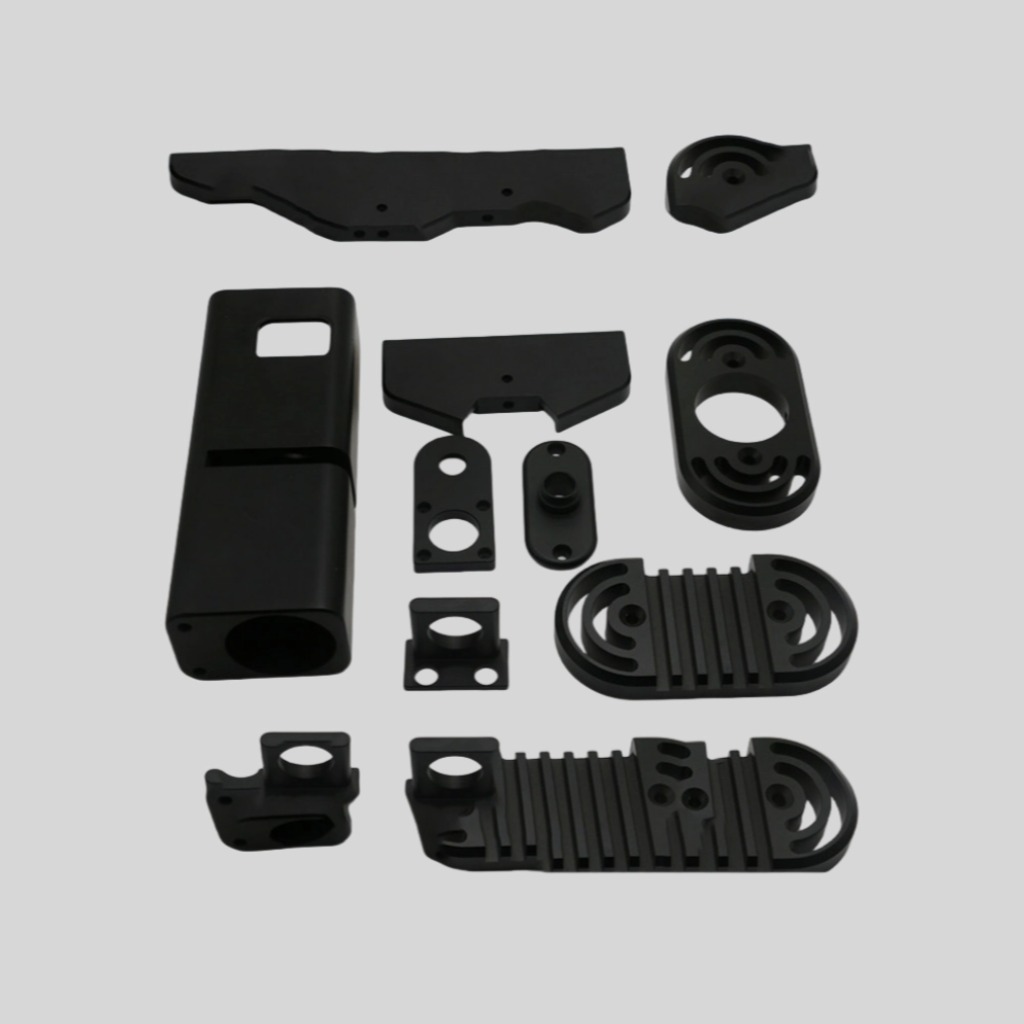
Precision CNC parts are mechanical components produced by computer numerical control equipment with dimensional tolerances often in the range of ±0.005 mm to ±0.01 mm, and in some ultra-precision cases down to ±0.001 mm. These parts typically feature complex 2.5D or 3D geometries, tight positional tolerances such as true position within 0.02 mm, and surface roughness targets of Ra 0.4 μm or better. A professional manufacturer or supplier must maintain stable dimensional repeatability over thousands of pieces, with process capability indices (Cp, Cpk) above 1.33 for critical dimensions to ensure reliable assembly and long service life.
Key Industrial Application Fields
Precision CNC components are widely used in automotive powertrain systems, aerospace structures, medical instruments, robotics, and semiconductor equipment. For example, engine valve seats or injector bodies may require geometric tolerances of parallelism and cylindricity within 0.01 mm, while surgical instruments demand burr-free edges and mirror-like surfaces to meet hygiene requirements. In automation equipment, precision shafts and linear guides must maintain coaxiality within 0.005 mm to reduce vibration and noise. In China, many high-end OEMs rely on specialized CNC part suppliers to support these demanding applications, especially in new energy vehicles (NEV) and high-speed rail industries.
Functional Requirements Driving Precision Levels
The required precision level of a CNC part derives from its functional role in the system. Rotating parts such as spindles, gears, and turbine components focus on concentricity, dynamic balance, and surface hardness. Static structural parts pay more attention to flatness, straightness, and rigidity. High-pressure hydraulic components require leak-tight fits with clearances as small as 2–5 μm, while optical and electronic housings often demand EMC shielding surfaces and tight enclosure fits to IP65 or higher. Understanding these functional metrics allows the manufacturer to determine suitable machining processes, inspection methods, and process control strategies from the outset.
From Design Concept To CNC Machining Blueprint
Engineering Requirements And Tolerance Analysis
Before any cutting occurs, engineers convert product requirements into a complete engineering drawing set, including dimensional chains, tolerance schemes, and surface specifications. For example, if a precision bushing must fit a shaft with a 25.000 mm nominal diameter and a clearance fit of 8–20 μm, the shaft may be specified as 24.988–24.992 mm and the bushing bore as 25.000–25.008 mm. This results in minimum clearance of 8 μm and maximum clearance of 20 μm. Such detailed tolerance analysis ensures that all mating parts produced by different suppliers in China or overseas can assemble without additional fitting or rework.
Material Selection, Heat Treatment, And Stability
The choice of material has a direct impact on machinability, dimensional stability, and service life. Common materials for precision CNC parts include alloy steels such as 40Cr and 42CrMo, stainless steels like 304 and 316L, aluminum alloys such as 6061 and 7075, and engineering plastics including POM and PEEK. Hardness after heat treatment is typically controlled in the range of HRC 28–36 for structural parts and HRC 58–62 for wear-resistant surfaces. Controlled heat treatment cycles with slow cooling or tempering minimize residual stress, reducing size variation after machining. An experienced manufacturer will validate hardness uniformity (e.g., ±2 HRC across the part) and dimensional distortion (e.g., less than 0.02 mm warpage over 100 mm length) before mass production.
Process Planning And Blueprint Optimization
Process engineers decompose each part into multiple machining stages, such as roughing, semi-finishing, and finishing, and allocate them to specific equipment such as CNC lathes, machining centers, and grinding machines. For complex parts, it is common to divide processing into 4–8 setups, with datum transfer plans defined to maintain geometric relationships. Engineers may adjust certain design details in consultation with the customer, such as modifying internal fillet radii to R0.5 instead of sharp corners to prolong tool life, or slightly increasing wall thickness from 0.5 mm to 0.8 mm to improve stability. These optimizations do not change the functional intent but significantly improve manufacturability and yield.
Translating CAD Models Into CAM Toolpaths
CAD Model Integrity And Data Management
The design department provides three-dimensional CAD models in formats such as STEP, IGES, or native CAD files. Before programming, CAM engineers verify that the model is complete, free of gaps, and matches the latest revision defined in the customer’s drawing list. A robust data management system links models, drawings, and process plans with version control, ensuring that all workshop programs are consistent with approved documentation. For safety-critical industries, traceability records may require retention for 10 years or more, recording every revision, approved supplier, machine, and operator code related to each batch of precision parts.
CAM Programming Strategies For Accuracy And Efficiency
Using CAM software, engineers generate toolpaths for milling, drilling, turning, and threading operations. For a precision cavity with complex freeform surfaces, they may use 3-axis or 5-axis simultaneous machining strategies with step-downs of 0.2–0.5 mm for roughing and 0.05–0.1 mm for finishing to control surface quality and geometric accuracy. Feed rates are typically set between 1000–3000 mm/min for roughing aluminum and 100–600 mm/min for finishing hardened steel, adjusted based on tool diameter and spindle speed. Programmers also optimize lead-in and lead-out paths, cutter compensation, and tool engagement angles to prevent chatter and maintain stable cutting forces.
Simulation, Verification, And NC Code Output
After programming, virtual simulation checks for collisions between the tool, holder, workpiece, and fixtures. Tool length compensation, machine travel limits, and safe start and end positions are verified against the real machine configuration. Simulation can detect over-travel or residual uncut areas before any physical setup, reducing scrap risk. Once confirmed, the CAM system posts the program into NC code compatible with the specific CNC controller. For a multi-operation part, dozens of toolpaths and hundreds or thousands of NC lines may be generated. A standardized naming convention, including part number, revision, and operation identifier, ensures clarity for the operator and quality team.
Selecting Suitable Materials For Precision Parts
Criteria For Metals, Alloys, And Plastics
Material selection balances mechanical performance, corrosion resistance, weight, and cost. For high-load gears and shafts, alloy steels with tensile strength of 800–1100 MPa and surface hardness above HRC 58 are common. For lightweight structural parts in aerospace or robotics, aluminum alloys with density around 2.7 g/cm³ and yield strength of 250–500 MPa are preferred. For chemical environments, stainless steels with corrosion resistance metrics such as pitting resistance equivalent number (PREN) above 30 may be specified. Precision plastic components may require dimensional stability within 0.05 mm over a 100 mm span despite temperature changes from -20 °C to +60 °C.
Material Certificates And Supplier Qualification
To ensure consistency, the manufacturer relies on qualified raw material suppliers that provide mill certificates with chemical composition, mechanical properties, and heat treatment records. Incoming material inspection typically includes spectrographic analysis to verify alloy content within ±0.1–0.2% for key elements, hardness checks, and visual inspection for surface defects. Batch numbers are recorded and linked to production orders, enabling complete backward traceability. In large production volumes, material traceability helps identify potential issues, such as micro-cracks or inclusions, before they affect thousands of finished parts shipped worldwide, including those exported from China to global markets.
Impact Of Material On Machining Strategy
Different materials dictate different cutting parameters, tool types, and coolant strategies. For example, aluminum alloys allow high-speed machining with spindle speeds of 10,000–24,000 rpm and removal rates above 5000 mm³/min using carbide end mills. Hardened steels require lower speeds, high rigidity machines, and possibly coated or ceramic tools. Plastics, particularly PEEK or PTFE, require sharp tools, low cutting forces, and controlled coolant application to prevent thermal deformation. The process engineer chooses tool geometry, flute count, and coating based on each material’s hardness, thermal conductivity, and chip formation behavior, balancing productivity and surface integrity.
Choosing The Right CNC Machines And Tools
Types Of CNC Equipment For Precision Work
Common equipment for precision part production includes CNC lathes with positioning accuracy of ±0.002 mm, vertical and horizontal machining centers with repeatability within ±0.003–0.005 mm, 4-axis and 5-axis machining centers for complex contours, and CNC grinders with sub-micron accuracy for critical surfaces. Machine rigidity, spindle power, and thermal stability are critical factors. For example, a high-precision machining center may have linear scale feedback systems with resolution of 0.0001 mm and spindle temperature control to maintain dimensional drift within 0.005 mm over an 8-hour shift. A capable supplier will configure its equipment portfolio according to the target industries and part types.
Cutting Tools, Inserts, And Tool Life Management
Tool selection includes solid carbide end mills, indexable inserts, drills, reamers, and specialized form tools. Tool diameter tolerance may be controlled within 0.003 mm for finishing cutters. Typical tool life is defined by flank wear of 0.2–0.3 mm or surface roughness increase beyond Ra 0.8 μm. To maintain consistent quality, shops often limit cutting tool life to 70–80% of the maximum possible, preventing sudden tool failure. Tool presetting devices measure tool length and diameter to micron-level accuracy before loading into the machine. Tool offset data is integrated into the NC program, ensuring that each new tool maintains the same reference as the previous one.
Fixture Design And Quick-Change Systems
Fixtures and workholding devices maintain part position and repeatability. A well-designed fixture uses hardened locating pins and ground surfaces to hold positioning error under 0.01 mm across repeated clamping cycles. Quick-change systems such as zero-point plates allow operators to swap fixtures within 1–2 minutes while maintaining repeatability within ±0.005 mm. For thin-walled or delicate parts, soft jaws and vacuum chucks distribute clamping force to prevent deformation. Fixture engineers also consider chip evacuation and coolant flow, ensuring that clamping elements do not hinder tool access or cause heat accumulation on critical surfaces.
Workholding, Positioning, And Machine Setup Steps
Datum Selection And Coordinate System Establishment
The choice of datums determines how the part’s dimensions and tolerances are realized. Typically, a primary planar surface is used as the base datum, complemented by secondary surfaces or locating features such as holes or slots. The machine’s work coordinate system (e.g., G54–G59) is set using a touch probe or edge finder, with alignment errors controlled within 0.005 mm and 0.02° for angular orientation. This ensures that each machining operation maintains the intended geometric relationship between features, such as keeping a hole pattern concentric within 0.01 mm to an external diameter.
Clamping Force, Deformation, And Thermal Effects
Improper clamping can cause elastic deformation, resulting in out-of-tolerance parts when unclamped. For thin plates of 2–3 mm thickness, clamping force must be carefully distributed, and machining paths should be balanced to minimize residual stress. Operators may use torque-limited wrenches to control clamping bolt torque within a narrow range, such as 8–10 N·m, based on fixture design. Thermal expansion is another factor: steel expands approximately 11–13 μm per meter per °C. A 100 mm long component may change length by about 1.1–1.3 μm per °C. Therefore, stable workshop temperatures, typically held between 20 ± 2 °C, are essential for reliable measurement and machining accuracy.
First-Piece Setup Validation And Approval
After setup, the operator machines a first-piece sample, which undergoes full inspection before mass production. This first-part verification checks key dimensions, tolerances, and surface roughness. Measurement tools may include micrometers with 0.001 mm resolution, height gauges, and coordinate measuring machines (CMMs) with probing uncertainty around 1.5–2.5 μm. If any deviation is found, engineers adjust tool offsets, program parameters, or fixture alignment. Only when all measured values fall within the specified tolerance, typically requiring at least 5–10 critical dimensions to be confirmed, is the batch approved for continuous production.
Executing Roughing And Finishing Machining Operations
Rough Machining For Material Removal
Roughing aims to remove the majority of excess material quickly while leaving a uniform allowance for finishing. Typical roughing allowances are 0.5–2.0 mm on surfaces, depending on part size and rigidity. For a steel block measuring 100 × 80 × 40 mm, roughing may remove up to 60–70% of the initial volume. Cutting parameters focus on high material removal rates, with deeper axial cuts and higher feed rates, while monitoring spindle load to avoid overload. During roughing, maintaining at least 0.5–1.0 mm of stock on precision surfaces helps absorb residual stress and prevent distortion during later finishing steps.
Semi-Finishing To Stabilize Geometry
Semi-finishing reduces the remaining allowance to a level suitable for the final pass, typically 0.1–0.3 mm, and helps even out residual stresses. This operation also refines the geometry, achieving intermediate surface roughness around Ra 1.6–3.2 μm. By machining in a stable clamping condition similar to the final setup, semi-finishing creates a “near-net” shape that minimizes springback during finishing. Dimensional consistency after this stage allows the process engineer to confirm that no large deformation is present. If necessary, parts can be stress-relieved by low-temperature heat treatment (e.g., 150–200 °C for several hours) before final finishing.
Finishing For Tolerances And Surface Quality
Finishing uses low cutting forces, fine stepovers, and precise toolpaths to achieve the defined tolerances and surface roughness. For example, a precision shaft with a nominal diameter of 20 mm and an IT6 tolerance may require a dimensional band of 10–16 μm, which can be achieved by finish turning followed by grinding or polishing. Surface roughness targets such as Ra 0.4 μm or better may use fine inserts with small nose radii (e.g., 0.2–0.4 mm) and cutting speeds optimized to avoid chatter. High-precision bores may be finished by reaming or honing to improve roundness and surface integrity, reaching tolerances of 0.005 mm or tighter.
Precision Measurement And In‑Process Quality Control
In-Process Gauging And Statistical Control
Precision manufacturing relies on continuous monitoring rather than only end-of-line inspection. Operators use in-process gauges, such as bore gauges with 0.001 mm resolution and digital calipers, to check key dimensions at defined intervals, for example every 10–30 pieces. Data may be recorded for statistical process control (SPC), calculating Cp and Cpk indices. A well-controlled process for a critical diameter may yield a Cp of 1.67 and Cpk above 1.33, indicating that the process mean is centered and variation is small. When trends show drift toward tolerance limits, adjustments are made promptly, preventing nonconforming batches and reducing scrap rates below 1–2%.
Final Inspection Using CMM And Optical Systems
Complex geometries and tight positional tolerances require advanced metrology equipment. Coordinate measuring machines can measure 3D features such as true position, flatness, and profile within microns. For example, a CMM with volumetric accuracy of (1.5 + L/350) μm can verify the position of hole patterns over 300 mm spans with uncertainty under 2.5 μm. Optical comparators and vision systems can quickly assess contours and edges, particularly for small or delicate parts where contact probes may be unsuitable. Inspection reports document all measured dimensions, material certificates, and process records, providing a comprehensive quality dossier for the customer.
Surface Integrity, Hardness, And Functional Testing
Besides dimensions, surface integrity affects fatigue strength, sealing performance, and wear resistance. Surface roughness is measured by profilometers, with typical requirements ranging from Ra 0.2–1.6 μm depending on functional needs. Hardness tests, such as Rockwell or Vickers, verify that heat-treated parts match specified values within ±2–3 HRC or ±10–20 HV. For sealing components, leak tests may be conducted at defined pressures, for example 10 bar for hydraulic fittings, with allowable leakage below 0.1 ml/min. Rotating assemblies may undergo dynamic balance tests to ISO G2.5 or G6.3 grades, ensuring vibration levels stay within acceptable limits during service.
Surface Treatment, Deburring, And Final Inspection
Deburring And Edge Finishing Processes
Machining inevitably generates burrs and sharp edges that can affect assembly and safety. Manual deburring with files and abrasive stones remains common for complex features, but automated methods such as vibratory finishing and thermal deburring are increasingly used for consistency. Edge radius requirements may be defined between 0.1–0.3 mm to ensure proper handling and assembly without compromising fit. For critical flow channels, burr-free internal passages prevent contamination and flow restriction. A professional CNC parts manufacturer defines clear deburring standards in work instructions, specifying tools, methods, and acceptance criteria to avoid over-deburring or under-deburring.
Surface Treatments For Performance Enhancement
Surface treatments improve corrosion resistance, hardness, or appearance. Typical processes include anodizing of aluminum to thicknesses of 10–25 μm, providing corrosion resistance for over 240 hours in salt spray tests; nickel or chrome plating for enhanced hardness and wear resistance; and black oxide coatings for mild steel components. For stainless steel parts, passivation removes free iron from the surface, improving corrosion behavior in saline or acidic environments. Coating thickness, adhesion, and uniformity are controlled via standardized procedures, and critical dimensions may be masked or compensated to account for coating growth, keeping final sizes within tight tolerances.
Comprehensive Final Verification And Documentation
After machining, deburring, and surface treatment, parts undergo final inspection to confirm compliance with dimensional, visual, and functional requirements. Inspectors check for scratches, dents, and coating defects under defined lighting conditions and often use magnification for small parts. All measurement data, heat treatment charts, and surface treatment certificates are compiled into a final inspection report or quality dossier. For batch production, sample sizes and acceptance quality limits (AQL) are determined according to international standards, balancing inspection workload with risk. Only after passing final inspection are parts released for packaging and shipment, ensuring that each delivered lot meets contractual and regulatory requirements.
Packaging, Traceability, And Continuous Process Improvement
Protective Packaging For Global Logistics
Precision parts are often shipped over long distances, including international routes from China to customers worldwide, so packaging must protect against corrosion, impact, and contamination. Components may be individually wrapped in VCI (volatile corrosion inhibitor) bags, separated by foam or plastic trays, and packed in sturdy cartons or wooden cases. Desiccants and humidity indicators are used when sea transport or long-term storage is expected. Packaging design considers stackability, weight distribution, and ease of identification, with clear labels indicating part number, batch number, quantity, and inspection status to simplify incoming inspection at the customer’s facility.
Traceability Systems And Digital Records
Each production batch is assigned a unique identification code linking it to raw material heats, machine numbers, operators, and inspection results. This traceability allows rapid root-cause analysis if issues arise after delivery. Digital production systems can record machine parameters, cutting times, and inspection values, forming a detailed process history. For high-value components, serialization down to individual part level may be implemented, with QR codes or laser-marked data matrices. These features support long product lifecycles, where components may be in service for 10–20 years and maintenance or replacement decisions rely on accurate manufacturing records.
Ongoing Optimization And Cost-Quality Balance
Continuous improvement focuses on reducing cycle time, scrap rate, and quality risks while maintaining or enhancing precision. Typical goals include annual scrap reduction by 20–30%, machine utilization above 75–80%, and on-time delivery exceeding 95%. Methods may include optimizing cutting parameters, upgrading tooling, improving coolant management, and enhancing operator training. Cost-benefit analysis evaluates whether investments in new machines, automation, or inspection technology yield sufficient gains in productivity and part quality. A professional CNC parts supplier balances these factors to offer competitive pricing and reliable lead times without compromising the demanding precision standards required by global customers.
Maxtech Provide Solutions
Maxtech focuses on providing high-precision CNC parts and assemblies for customers who require reliable, repeatable results. With a strong engineering team and advanced CNC equipment, Maxtech supports projects from prototype to mass production, helping optimize designs, materials, and processes. The company maintains strict quality control through CMM inspection, SPC, and full traceability, serving customers in China and around the world as a trusted manufacturer and supplier. Whether you need tight-tolerance shafts, complex housings, or precision fixtures, Maxtech offers efficient production, stable quality, and responsive technical support tailored to your application requirements.
Post time: 2025-12-11 18:12:04
 Privacy settings